Showing posts with label led. Show all posts

Friday, November 14, 2014

Simple 110 and 220V AC LED Voltage Indicator

This circuit, designed on request, has proven to be useful to indicate when the voltage in a power supply line is changing from 120V to 240Vac. It can be used in different circumstances and circuits, mainly when an increase in ac or dc supply voltage needs to be detected. D3 illuminates when the line voltage is approaching 120V and will remain in the on state also at 240V supply. On the other hand, D6 will illuminate only when the line voltage is about 240V and will stay on because the latching action of Q1, Q2 and related components. C1, D1 and D2 provide a low dc voltage in the 4.5V - 6V range in order to allow proper operation of latch circuit and LEDs.

Circuit diagram


Parts:

  • R1_____________470R 1/2W Resistor
  • R2_____________220K 1/4W Resistor
  • R3,R7__________470R 1/4W Resistors
  • R4_______________1K 1/4W Resistor
  • R5_______________2K2 1/4W Resistor
  • R6_____________330R 1/4W Resistor
  • C1_____________330nF 630V Polyester Capacitor
  • C2______________10µF 25V Electrolytic Capacitor
  • D1,D2________1N4007 1000V 1A Diode
  • D3,D6___________LEDs (Color and shape at will)
  • D4_________BZX79C10 10V 500mW Zener Diode (See Notes)
  • D5___________1N4148 75V 150mA Diode
  • Q1____________BC547 45V 100mA NPN Transistor
  • Q2____________BC557 45V 100mA PNP Transistor

Notes:

  • D4 value could require some adjustment in order to allow precise switching of the circuit at the chosen voltage. If the case, please try values in the 8.2V - 15V range.
  • Warning! The circuit is connected to 240Vac mains, then some parts in the circuit board are subjected to lethal potential! Avoid touching the circuit when plugged and enclose it in a plastic box.
Read More..

Tuesday, November 4, 2014

Simple LED Bike Light

On my mountain bike I always used to have one of those well-known flashing LED lights from the high street shop. These often gave me trouble with flat batteries and lights that fell off. As an electronics student I thought: “this can be done better”. First I bought another front wheel, one which has a dynamo already built in the hub. This supplied a nice sine wave of 30 Vpp (at no load). 

With this knowledge I designed a simple power supply. The transistors that are used are type BD911.These are a bit of an over-kill, but there were plenty of these at my school, so that is why I used them. Something a little smaller will also work. The power supply is connected to an astable multi-vibrator. This alternately drives the front light and the rear light. The frequency is determined by the RC time-constant of R3 and C3, and R2 and C4. This time can be calculated with the formula: t = R3×C3 = 20×103×10×10-6 = 0.2 s You can use a 22k (common value) for R2 and R3, that doesn’t make much difference. On a small piece of prototyping board are six LEDs with a voltage dropping resistor in series with each pair of LEDs.

LED Bike Light Circuit Diagram:

Light

Such a PCB is used for both the front and the rear of the bike. Of course, you use white LEDs for the front and red ones for the rear. The PCB with the main circuit is mounted under the seat, where it is safe and has been working for more than a year now. There are a few things I would change for the next revision. An on/off switch would be nice. And if the whole circuit was built with SMD parts it could be mounted near the front light. This would also be more convenient when routing the wiring. Now the cable from the dynamo goes all the way to the seat and from there to the front and rear lights.


Read More..

Sunday, November 2, 2014

LM3433 4A to 20A LED DRIVER EVALUATION BOARD ELECTRONIC DIAGRAM


LM3433 4A to 20A LED DRIVER EVALUATION BOARD ELECTRONIC DIAGRAM

LM3433 is an adaptive constant on-time DC/DC buck constant current controller designed to drive a high brightness LEDs (HB LED) at high forward currents. It is a true current source that provides a constant current with constant ripple current regardless of the LED forward voltage drop. The board can accept an input voltage ranging from -9V to -14V w.r.t. GND. The output configuration allows the anodes of multiple LEDs to be tied directly to the ground referenced chassis for maximum heat sink efficacy when a negative input voltage is used.
Read More..

Thursday, October 23, 2014

Diagram Running LED with 4017

Running LED with 4017 complete with PCB layout. The series of 8 LED current is the basis for creating an 8-point LED. Slightly different from the running LED with IC 4017 (decade counter), 8 running this led is lit in sequence, but that has been previously flame does not die when the led is lit afterwards. 8 led to death after led to the fire-8. Meanwhile in the running LED (decade counter), the system LED lights like "point", there is only one LED that flashes between the tenth led.

Running

The main component is the IC 74LS164 (SHIFT REGISTER), with its timer is astable multivibrator circuit (using IC NE555).

The series will be more efficient when using a stable power supply (regulator) using IC Regulator 7805. Under this scheme a series of stable power supply 5 volts dc.

rangkaian

Read More..

Wednesday, October 22, 2014

Flip Flop Led Circuit

Flip flop circuit is a series of free runing multivibrator given the burden of LEDs on each side of the transition changes its output signal. Flip flop circuit with LEDs is quite simple, that is prepared with 2 units and 2 units of 2N3904 transistor circuit tank circuit composed by the RC circuit. 
LED indicators signal a change that is placed on each side of the flip flop will be lit in turn by the fire and extinguished the same as the charge and discharge capacitor. Flip flop circuit is quite simple as shown in the picture below.

Flip Flop LED series

The working principle is the flip flop over when the series voltage source is given then the 10uF capacitor will be charged through R 470 and the LED will then be forwarded to triger the transistor base so that the transistor will turn ON and LEDs. this occurs alternately on each side, so that the LED light will illuminate in turn as well.
Read More..

Saturday, October 18, 2014

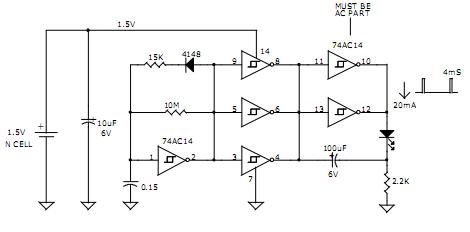
1 5V LED FLASHER CIRCUIT

1.5V LED FLASHER CIRCUIT

1.5V LED FLASHER CIRCUIT
AVERAGE CURRENT = 120uA
PEAK LED CURRENT = 20mA
4mS PULSE  1 FLASHE/SEC
APPROX. 6 MONTHS OPPERATION FROM N-CELL
APPROX. 12 MONTHS OPPERATION FROM AA CELL

DAVID JOHNSON AND ASSOCIATES
Read More..

Thursday, October 9, 2014

Solar Power walkway marker Led display

Solar

These are the little lights with the stake on the bottom that you can push into the ground along your driveway or sidewalk and have the solar panel on top. The solar cell charges a AA NiCd battery during the day and at night the battery powers the LED. The circuit board in this particular model was originally designed to hold a pair of 5mm amber LEDs, but the manufacturer apparently found a source of higher power 10mm amber LEDs and the final product only needs one of these. Due to the limited space, many of the components are surface mount. The transistors are both 2N3904 equivalent surface mounts. Unfortunately, the capacitor is also surface mount and is unmarked.

The charging circuit is fairly simple and has a photovoltaic solar cell to charge the battery and a diode to prevent the battery from powering the cell when it’s dark. Now moving along, there is a cadmium sulphide (CdS) photo resistor, a 10k resistor and a 1k resistor that forms a voltage divider at the base of Q1. When light hits the photo resistor, it has a low resistance which is amplified by the transistor. The collector is tied to the base of the left hand transistor, so when it’s on it clamps its base to ground and prevents it from oscillating. When it’s dark and the CdS Cell has a high resistance, the right transistor is off which allows the rest of the circuit to begin oscillating.

Read More..

Thursday, October 2, 2014

Simple AC Line Circuit Using LED Indicator

The circuit in the figure illustrates to power a LED from the 120 volt AC line using a capacitor to drop the voltage and a small resistor to limit the inrush current. This circuit can operate one or two LED. There are three concept to operate the LEDs. Operation of this circuit is when the capacitor must pass current in both direction, a small diode is connected in parallel with the LED to provide a path for the negative half cycle and also to limit the reverse voltage across the LED. A second LED with the polarity reversed may be substituted for the diode, or a tri-color LED could be used which would appear orange with alternating current.


The circuit is fairly efficient and draws only about a half watt from the line. The resistor value (1K / half watt) was chosen to limit the worst case inrush current to about 150 mA which will drop to less than 30 mA in a millisecond as the capacitor charges. This appears to be a safe values, I have switched the circuit on and off many times without damage to the LED. The 0.47 uF capacitor has a reactance of 5600 ohms at 60 cycles so the LED current is about 20 mA half wave, or 10 mA averages. A larger capacitor will increase the current and a smaller one will reduce it. The capacitor must be a non-polarized type with a voltage rating of 200 volts or more.
The lower circuit is an example of obtaining a low regulated voltage from the AC line. The zener diode serves as a regulator and also provides a path for the negative half cycle current when it conducts in the forward direction. In this example the output voltage is about 5 volts and will provide over 30 milliamps with about 300 millivolts of ripple. Use caution when operating any circuits connected directly to the AC line.
Read More..

Saturday, September 6, 2014

110 and 220V AC LED Voltage Indicator

110 and 220V AC LED Voltage Indicator Circuit Diagram. Useful for power lines control, Simple, transformer less schemary. This schema, designed on request, has proven to be useful to indicate when the voltage in a power supply line is changing from 120V to 240Vac. It can be used in different circumstances and diagram, mainly when an increase in ac or dc supply voltage needs to be detected. D3 illuminates when the line voltage is approaching 120V and will remain in the on state also at 240V supply. On the other hand, D6 will illuminate only when the line voltage is about 240V and will stay on because the latching action of Q1, Q2 and related components. C1, D1 and D2 provide a low dc voltage in the 4.5V - 6V range in order to allow proper operation of latch schema and LEDs.

Circuit diagram:
110-220vac-voltage-
110 and 220V AC LED Voltage Indicator Circuit Diagram

Parts:
R1__________470R 1/2W Resistor
R2__________220K 1/4W Resistor
R3,R7_______470R 1/4W Resistors
R4__________1K 1/4W Resistor
R5__________2K2 1/4W Resistor
R6_________330R 1/4W Resistor
C1_________330nF 630V Polyester Capacitor
C2_________10µF 25V Electrolytic Capacitor
D1,D2______N4007 1000V 1A Diode
D3,D6______LEDs (Color and shape at will)
D4_________BZX79C10 10V 500mW Zener Diode (See Notes)
D5_________1N4148 75V 150mA Diode
Q1_________BC547 45V 100mA NPN Transistor
Q2_________BC557 45V 100mA PNP Transistor

Notes:
  • D4 value could require some adjustment in order to allow precise switching of the schema at the chosen voltage. If the case, please try values in the 8.2V - 15V range.
  • Warning! The schema is connected to 240Vac mains, then some parts in the schema board are subjected to lethal potential! Avoid touching the schema when plugged and enclose it in a plastic box.
Read More..

Wednesday, September 3, 2014

LED Pulsere circuit for the Christmas Star


This schema can be used to decorate your Christmas star.Here the LED light up gradually and disappear gradually.you can attach 6 LEDs for this.Supply 4.5v - 6v for this schema.Here we have used femous IC LM358 .So you all will be able to find that IC easily.


Parts

IC1__________LM358 Low Power Dual Op-amp

Q1___________BC337 45V 800mA NPN Transistor

R1,R2___________4K7 1/4W Resistors

R3_____________22K 1/4W Resistor

R4______________2M2 1/4W Resistor

R5_____________10K 1/4W Resistor

R6_____________47R 1/4W Resistor

C1______________1µF 63V Polyester Capacitor

D1_____________5mm. Red LED


Read More..

Monday, September 1, 2014

Running LED

This is the running LED schema diagram. The LED will "running" (on) one by one. You can use this schema for many purpose like motorcycle lamp, running character and much more.

Here the schematic diagram with IC timer 555:
Running

And use this schema use NAND logic:
Running
Read More..

Sunday, August 31, 2014

LED Flasher for Cars and Motorcycles Wiring diagram Schematic

This is a flasher that uses 4 high brightness LEDs that can be used in Automotive, Motorcycle or bicycle. It uses the IC 555 which is a monostable to adjust the flasher you can use the RV1, which can be a potentiometer or trim pot 100k. If built in SMD it fits within the own flashlight.

 LED Flasher for Cars and Motorcycles Circuit Diagram

LED

Read More..

Thursday, August 28, 2014

Dark activated LED or Lamp Flasher

This schema adopts the rather unusual Bowes/White emitter coupled multivibrator schema. The oscillation frequency is about 1Hz and is set by C1 value. The LED starts flashing when the photo resistor is scarcely illuminated. The onset of flashing can be set by trimming R2.


Dark-activated


Parts:

R1_________________Photo resistor (any type)
R2________________100K 1/2W Trimmer Cermet
R3,R4______________10K 1/4W Resistors
R5________________470R 1/4W Resistor
R6_________________47R 1/4W Resistor

C1________________220µF 25V Electrolytic Capacitor

D1______________1N4148 75V 150mA Diode
D2_________________LED Any type and color (See Notes)

Q1,Q2____________BC337 45V 800mA NPN Transistors

SW1_______________SPST Switch

B1__________________3V (Two 1.5V AA or AAA cells in series, etc.)


Notes:

* Best results in flashing frequency can be obtained using for C1 a value in the 100 - 1000µF range.
* To drive a filament lamp make the following changes:

Use a 2.2 to 3V, 250-300mA bulb in place of the LED
R2 = 10K 1/2W Trimmer Cermet
R3, R4 = 1K 1/4W Resistors
R6 = 1R 1/4W Resistor
C1 = 470 to 1000µF 25V Electrolytic Capacitor

* In LED-mode operation the stand-by current consumption is less than 400µA.
* In Lamp-mode operation the stand-by current consumption is about 3mA.


Read More..

Saturday, August 23, 2014

Simple LED Matrix Horizontally Wiring diagram Schematic

This is a Simple LED Matrix Horizontally Circuit Diagram. LEDs provide a befitting way to electronically display information. whereas the seven-segment LED brandish, organized in the pattern of the digit 8, is common, it does not permit the brandish of some alphanumeric individual features. A 5×7 commanded matrix permits the display of all ASCII individual features, as well as graphics shapes.

The schema in this conceive concept displays an unconventional way to use a 5×7 LED matrix.You can use a conceive encompassing a set of 5×7 commanded flats without altering any thing in the schemary, except for the arrangement of the commanded units.

Simple LED Matrix Horizontally Circuit Diagram


 Using one 5×7 LED matrix, or N units, horizontally instead of vertically allows the display of two characters, or 2×N characters. The minimum pattern for lowercase and uppercase letters requires only a 3×5 LED configuration, except for the letters M and m, which require at least a 5×5 LED configuration and need a dedicated subroutine.

The schema in Figure 1 uses an 8-bit, 18-pin PIC micro controller and a decade counter to drive one or two 5×7 LED units to provide a display module of two or four digits. The schema uses a small push button switch to increment the counter. By default, the schema works in high-brightness mode. If you press the push button during power-on, the schema works in low-power mode.
Read More..

Thursday, August 21, 2014

Temperature Candle Using LED

LED based projects require a lot of skill and hence only experienced schema designers try out these diagram. But there are also a few diagram in this genre that can be done by amateur electronic hobbyists. The temperature candle is one such schema. Read on to know more about this.

Hacks

The hardware components that are required to build this schema are listed below:
  • Microcontroller
  • Temperature Sensor
  • RGB LED
  • PCB

The schema design is pretty simple. The LED is made to flicker by the microcontroller and the color is based on the ambient temperature at that point. The temperature of the room can be known by observing the color of the LED.

The temperature value is obtained in degree Celsius. This value is received as a result of pressing the reset button on the PCB. This value can also be obtained by providing power to the device. Once the device is powered up, the change in temperature is indicated. The blue LED is triggered for a temperature increase of 10 degrees. The red LED is triggered for a temperature increase of a single degree.
Suppose, the ambient temperature is 23 degrees celsius, The schema works in such a way that the blue LED is made to blink twice and the red LED is made to blink 3 times. Soon after this, an orange colored flicker is observed as the LED goes into canfle mode.

Since through hole components are used in this schema, it is very cheap to construct and the components can be easily soldered. The schema also contains a jack for connecting to a Microchip Pickit 3 programmer / debugger. This reduces the complexity involved in code modification and download.
Read More..

LED Multivibrator Circuir Diagarm


This is famous LED schema diagram.You can operate this schema with 9V power supply.If you want to change the speed of the LED bulbs you can change the value of 100K resistor.


Note build this schema on a pcb
Read More..