Thursday, November 13, 2014
TT6061A and TT8486A sensitive touch light dimmer circuit with explanation
Initially, when mains switch is ‘on,’ the bulb is ‘off’. Now, if you touch the touch plate, the bulb glows dimly. On second touch, the bulb gives medium light. At the third touch, the bulb is driven fully and another touch puts off the light.
This sensitive touch light dimmer circuit uses minimum external components and can be used for 110V or 220V AC by simply changing some external components . For touch plate, you can use a simple copper plate of 1cm×1cm (a small piece of PCB) or even the end of the lead wire. Touch plate is coupled to the touch detector through 1000pF, 2kV capacitors C4, C5 connected in series. Internally IC TT6061A’s touch signal is connected to the counter/ decoder via a resistor and clock input CK is connected to the counter/decoder via a frequency generator.
Line frequency signal is taken through R4 at pin 2 of IC TT6061A. At zero crossing, the triac (BT136) triggers to drive a 200W bulb.
This light dimmer circuit require a 6.8 volts power supply, which is taken directly from mains through resistors R2, diode D1, capacitor C2, and zener diode and fed to power-input pin 3 of the IC. Capacitors C4, C5 connected between touch input pin 4 and touch plate remove the shock potential from the touch plate, so do not replace these capacitors with a single capacitor or with a capacitor of a lower voltage rating.
Te circuit diagram shown here is just for 110 volts ac , if you want to use this touch sensitivity light dimmer for 220 volts AC , you need to chance some components value .For 220 volts usage you’ll need to change R1 510K TO 620K ( FOR 60HZ CHANGE TO 50HZ ) , R2 20K/1W TO 40K/2W ( FOR 110V CHANGE TO 220V ) and R6 1M TO 1.5M ( FOR 110V CHANGE TO 220V ) and also you can add an additional capacitor in series with the C4 and C5 ( capacitor used must be the same type an value ) .
S: electroniq.net/other-projects/tt8486a-tt6061a-sensitive-touch-light-dimmer.html

Tuesday, November 4, 2014
Simple LED Bike Light
Thursday, October 16, 2014
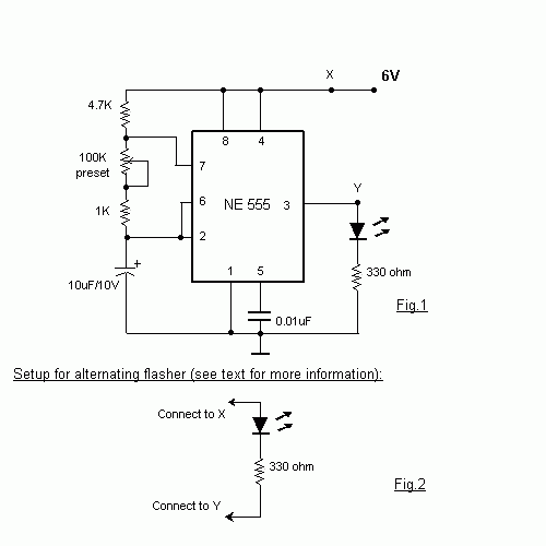
New Light Flasher Circuit Diagram
Wednesday, October 8, 2014
LASCR Light Activated SCR circuit
LASCR or Photo SCR
Light activated SCR (LASCR) or a Photo SCR is just an ordinary SCR except that it can also be light triggered. Most LASCRs also have a gate terminal for being triggered by an electrical pulse just as a conventional SCR. The basic construction of an LASCR is shown in figure. The schematic symbols most commonly used for the LASCR are shown in figure. Some LASCRs have clear windows in their cases so that light sources from other devices can be coupled to them. Many have the light source encapsulated in the same package so that a relay is formed. When the light falling on depletion layers is strong enough, valence electrons are dislodged from their orbits and become free electrons. When these free electrons flow out of the collector of one, transistor into the base of the other.
LASCR Symbol
The positive feedback starts and the LASCR turns on just like a normal SCR, the LASCR will continue to conduct even if the light source is removed. For maximum sensitivity to light, the gate is left open, as shown in figure. Trigger adjust can be included if an adjustable trip point is desired as shown in figure. The gate resistor diverts some of the light produced electrons and alters the sensitivity of the circuit to the incoming light. The devices are for low power applications.
LASCR Applications
Relay with LASCR
Relay using LASCR
Tuesday, September 2, 2014
Light activated switch circuit
This schema is well important schema for us because We can get lots of advantages through this schema.When the light puts on L.D.R the schema activates.So you can use this one as you morning alarm or you can use this one for your robot.
Note
# You can use either a 12 V battery or a well regulated & filtered 12V DC mains operated power supply.
# The pin 5&6 (Balance & Balance/Strobe ) of IC LM311 are shorted to minimize the chance of oscillations.
Thursday, August 28, 2014
Running Light circuit uses a CMOS 555 timer
| Running Light circuit uses a CMOS 555 timer |