Showing posts with label flasher. Show all posts
Showing posts with label flasher. Show all posts
Saturday, October 18, 2014
1 5V LED FLASHER CIRCUIT
1.5V LED FLASHER CIRCUIT
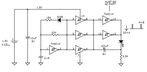
1.5V LED FLASHER CIRCUIT
AVERAGE CURRENT = 120uA
PEAK LED CURRENT = 20mA
4mS PULSE 1 FLASHE/SEC
APPROX. 6 MONTHS OPPERATION FROM N-CELL
APPROX. 12 MONTHS OPPERATION FROM AA CELL
DAVID JOHNSON AND ASSOCIATES

Thursday, October 16, 2014
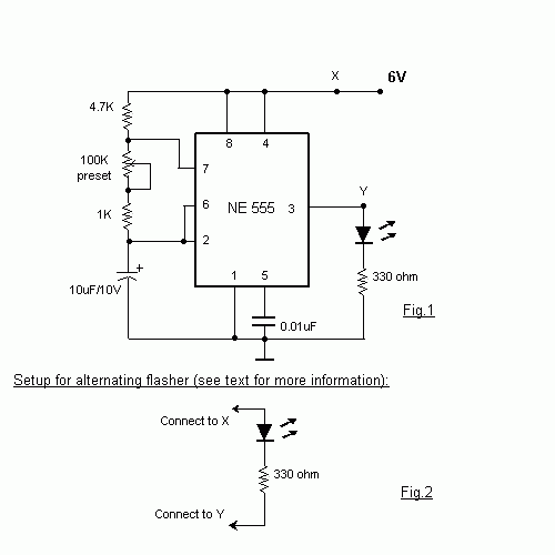
New Light Flasher Circuit Diagram
This is a very basic circuit for flashing one or more LEDS and also to alternately flash one or more LEDs.It uses a 555 timer setup as an astable multivibrator with a variable frequency.With the preset at its max. the flashing rate of the LED is about 1/2 a second. It can be increased by increasing the value of the capacitor from 10uF to a higher value.
For example if it is increased to 22uF the flashing rate becomes 1 second. There is also provision to convert it into an alternating flasher. You just have to connect a LED and a 330ohm as shown in Fig.2 to the points X and Y of Fig.1. Then both the LEDs flash alternately.Since the 555 can supply or sink in upto 200mA of current, you can connect upto about 18 LEDS in parallel both for the flasher and alternating flasher (that makes a total of 36 LEDs for alternating flasher).
Light Flasher Circuit Diagram
Sunday, August 31, 2014
LED Flasher for Cars and Motorcycles Wiring diagram Schematic
This is a flasher that uses 4 high brightness LEDs that can be used in Automotive, Motorcycle or bicycle. It uses the IC 555 which is a monostable to adjust the flasher you can use the RV1, which can be a potentiometer or trim pot 100k. If built in SMD it fits within the own flashlight.
LED Flasher for Cars and Motorcycles Circuit Diagram
Thursday, August 28, 2014
Dark activated LED or Lamp Flasher
This schema adopts the rather unusual Bowes/White emitter coupled multivibrator schema. The oscillation frequency is about 1Hz and is set by C1 value. The LED starts flashing when the photo resistor is scarcely illuminated. The onset of flashing can be set by trimming R2.

Parts:
R1_________________Photo resistor (any type)
R2________________100K 1/2W Trimmer Cermet
R3,R4______________10K 1/4W Resistors
R5________________470R 1/4W Resistor
R6_________________47R 1/4W Resistor
C1________________220µF 25V Electrolytic Capacitor
D1______________1N4148 75V 150mA Diode
D2_________________LED Any type and color (See Notes)
Q1,Q2____________BC337 45V 800mA NPN Transistors
SW1_______________SPST Switch
B1__________________3V (Two 1.5V AA or AAA cells in series, etc.)
Notes:
* Best results in flashing frequency can be obtained using for C1 a value in the 100 - 1000µF range.
* To drive a filament lamp make the following changes:
Use a 2.2 to 3V, 250-300mA bulb in place of the LED
R2 = 10K 1/2W Trimmer Cermet
R3, R4 = 1K 1/4W Resistors
R6 = 1R 1/4W Resistor
C1 = 470 to 1000µF 25V Electrolytic Capacitor
* In LED-mode operation the stand-by current consumption is less than 400µA.
* In Lamp-mode operation the stand-by current consumption is about 3mA.
Read More..
Parts:
R1_________________Photo resistor (any type)
R2________________100K 1/2W Trimmer Cermet
R3,R4______________10K 1/4W Resistors
R5________________470R 1/4W Resistor
R6_________________47R 1/4W Resistor
C1________________220µF 25V Electrolytic Capacitor
D1______________1N4148 75V 150mA Diode
D2_________________LED Any type and color (See Notes)
Q1,Q2____________BC337 45V 800mA NPN Transistors
SW1_______________SPST Switch
B1__________________3V (Two 1.5V AA or AAA cells in series, etc.)
Notes:
* Best results in flashing frequency can be obtained using for C1 a value in the 100 - 1000µF range.
* To drive a filament lamp make the following changes:
Use a 2.2 to 3V, 250-300mA bulb in place of the LED
R2 = 10K 1/2W Trimmer Cermet
R3, R4 = 1K 1/4W Resistors
R6 = 1R 1/4W Resistor
C1 = 470 to 1000µF 25V Electrolytic Capacitor
* In LED-mode operation the stand-by current consumption is less than 400µA.
* In Lamp-mode operation the stand-by current consumption is about 3mA.
Subscribe to:
Posts (Atom)