Showing posts with label 1. Show all posts
Showing posts with label 1. Show all posts
Saturday, October 18, 2014
1 5V LED FLASHER CIRCUIT
1.5V LED FLASHER CIRCUIT
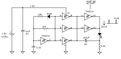
1.5V LED FLASHER CIRCUIT
AVERAGE CURRENT = 120uA
PEAK LED CURRENT = 20mA
4mS PULSE 1 FLASHE/SEC
APPROX. 6 MONTHS OPPERATION FROM N-CELL
APPROX. 12 MONTHS OPPERATION FROM AA CELL
DAVID JOHNSON AND ASSOCIATES

Friday, October 17, 2014
Radio only 1 transistor without electricity
Experts and amateurs have been Experimenting with radios without batteries since the wireless communication started.
In many designs weve seen radios that operate without power, but all are known to use the diode 1N34. (Crystal Radio).
In many designs weve seen radios that operate without power, but all are known to use the diode 1N34. (Crystal Radio).
Although significant improvements have increased the sensitivity and selectivity of these system circuits, Performances were limited until new techniques have emerged.
Here we have the first transistor radio that works without batteries, it is powered by random electric fields are everywhere in the atmosphere.

These circuits are relatively cheap to manufacture, have more volume and better reception from the crystal radios.
This circuit is a medium wave receiver and attaches easily to frequencies from 500Khz to 11Mhz.
To get good results in the reception of radio stations, we should give great importance to the ground and the antenna.
To listen to distant and weak stations we have to use a battery 9volt parallel with the capacitor C4 with its positive side between R2 and C4.
The coils are in the frequency of 500-1500Khz is tight and closely wrapped.
The coils are in frequency of 1.5-11Mhz is more tighter and more closely wrapped.
This circuit is a medium wave receiver and attaches easily to frequencies from 500Khz to 11Mhz.
To get good results in the reception of radio stations, we should give great importance to the ground and the antenna.
To listen to distant and weak stations we have to use a battery 9volt parallel with the capacitor C4 with its positive side between R2 and C4.
The coils are in the frequency of 500-1500Khz is tight and closely wrapped.
The coils are in frequency of 1.5-11Mhz is more tighter and more closely wrapped.
Friday, September 12, 2014
Latest Tab Google captures your 3D environment It cost U S 1 024
Google introduces its tablet the Tango Project, a project that handles allow you to create 3D maps of the environment of a mobile device.
The Project Tango Tablet, as Google calls it for now, is mainly designed for developers interested in exploring the future of 3D technology on a mobile device can do so and to develop new features that may allow it to another level bringing this technology, as mentioned Google.
The 7-inch tablet that goes on sale later this year is priced at U.S. $ 1.024, making it not the cheapest in the market.
However, Googles tablet was created with help from Nvidia to allow create internal maps of buildings in 3D, thanks to various cameras and sensors that are in the device. The tablet has a Nvidia Tegra K1 processor, 4GB of RAM, 128GB of storage, Wi-Fi and 4G LTE.
Although the Tango Project or Project Tango would be in its initial phase, the new tablet could help take an important step for this kind of technology can reach consumers in the future.
Thursday, September 11, 2014
BUZ23 MOSFET Audio Amplifier 1 x 240W
BUZ23 MOSFET general description:
A high power audio amplifier circuit which can output up to 240W on a 4Ω speaker.
This mosfet amplifier is built with BUZ23 and uses a 40V symmetrical power supply. Connect the NTC close to the heatsinker.BUZ23 MOSFET circuit diagram:

Saturday, September 6, 2014
TDA7490 Audio Amplifier 2 x 25W 1 x 50W
TDA7490general description:

The TDA7490 is a dual audio class D amplifier assembled in Flexiwatt 25 package; it is specially designed for high efficiency application mainly for TV and Home Stereo sets. TDA7490 Audio Amplifier 2 x 25W / 1 x 50W
TDA7490 features:
- 25W + 25W OUTPUT POWER:
- RL = 8Ω/4Ω; THD = 10%
- HIGH EFFICIENCY
- WIDE SUPPLY VOLTAGE RANGE (FROM
- ±10 TO ±25V)
- SPLIT SUPPLY
- TURN OFF/ON POP FREE
- ST-BY AND MUTE FEATURES
- SHORT CIRCUIT PROTECTION ACROSS
- THE LOAD
- THERMAL OVERLOAD PROTECTION
- EXTERNALLY SINCHRONIZABLE
- BRIDGE CONFIGURATION
TDA7490 sterio circuit diagram:
 |
| TDA7490 Audio Amplifier 2 x 25W / 1 x 50W circuit diagram |
TDA7490 mono circuit diagram:
 |
| TDA7490 Audio Amplifier 2 x 25W / 1 x 50W mono circuit diagram |
TDA7490 sterio circuit pcb:
 |
| TDA 7490 pcb layout |
Wednesday, September 3, 2014
Power Supply Variable 1 3V 12 2V 1A Circuit
Power supply circuit to generate output below were variations between 1.3V DC to 12.2V DC with 1A current.
In addition, the power supply circuit is also equipped with over-current protection or shield against belebih flow. Power supply circuit is very simple, but the quality is quite good, made her basiskan regulator IC LM723 is a pretty legendary.
In addition, the power supply circuit is also equipped with over-current protection or shield against belebih flow. Power supply circuit is very simple, but the quality is quite good, made her basiskan regulator IC LM723 is a pretty legendary.
Description:
R2 to set the output voltage. The maximum current is determined by R3, over-current protection circuit inside the LM723 to detect the voltage on R3, if it reaches 0.65 V, the voltage output will be off her. So the current through R3 can not exceed 0.65 / R3 although output short-circuit in his.
C3 and C4 are ceramic capacitors, as much as possible directly soldered to the PCB, this is because the LM723 is prone to oscillation that is not cool.
LM723 works with 9.5V input voltage to 40 V DC and the LM723 can generate its own current of 150mA when the output voltage is not more than 6-7V under input voltage.
Specifications:
Output (value estimated):
Vmin = (R4 + R5) / (R5 * 1.3)
Vmax = (7.15 / R5) * (R4 + R5)
Imax = 0.65/R3
Max. Power on R3: 0.42/R3
Min. DC Input Voltage (pin 12 to pin 7): Vmax + 5
Component List:
B1 40V/2.5A
C1 2200uF (3300uF even better)
C2 4.7uF
C3 100nF
C4 1NF
C5 330nF
C6 100uF
Green LED D1
D2 1N4003
F1 0.2A F
F2 2A M
IC1 LM723 (in a DIL14 plastic package)
R1 1k
R2 Pot. 5k
R3 0.56R/2W
R4 3.3k
R5 4.7k
S1 250V/1A
T1 2N3055 on a heatsink 5K / W
TR1 220V/17V/1.5
Subscribe to:
Posts (Atom)