Showing posts with label stereo. Show all posts
Showing posts with label stereo. Show all posts
Wednesday, November 19, 2014
3W Stereo Amplifier schematic
3 Watt stereo amplifier circuitusing MAX 7910 IC. The MAX9710 a stereo audio power amplifier IC capable of delivering 3Watts of out put to 4 Ohm loads. MAX9710 can be operated from a single 4.5V to 5.5V power supply , makes it ideal for hand held applications.The IC for 3 Watt stereo amplifier circuit also features thermal overload protection.
Circuit Schematics 3 Watt Stereo Amplifier MAX 7910
| 3 Watt stereo amplifier circuit |
This 3 Watt stereo amplifier circuit is suitable for small power audio devices such as radio sets and portable CD players. 5 V DC power supply is used for powering the 3 Watt stereo amplifier circuit. 6V battery with an IN 4007 diode series to the positive terminal of it can also be used instead of 5 V DC supply. The 3 Watt stereo amplifier circuit will get a supply voltage approximately 5 V after 0.7 V voltage drop across diode.

Thursday, October 30, 2014
Mono to Stereo Audio Signal Circuit Converter
This circuit is used to convert a mono audio signal into a stereo signal that can be panned between the left and right channel by a 0-10V control signal, it is intended for analog synthesizer systems.
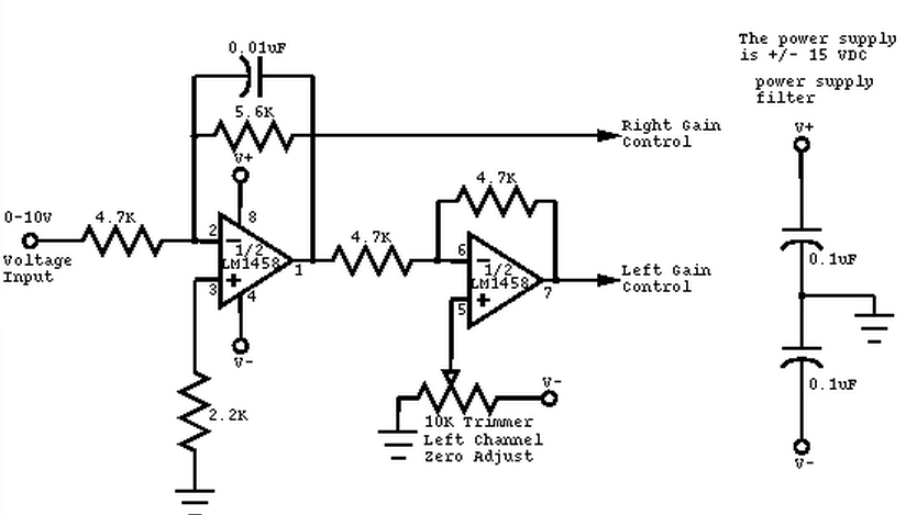 |
| Circuit Convert Mono to Stereo Audio Signal Schematic |
Stereo PC Speaker Powered USB Speaker
This is the circuit diagram of USB powered computer speaker, or it widely known as multimedia speakers for PCs. The circuit has single-chipbased design, low-voltage electrical power supply, compatibility with USB power from computer, simple heat-sinking, inexpensive, large flexibility and wide temperature tolerance.
At the heart of the circuit is IC TDA2822M. This IC is, actually, monolithic type in 8-lead mini DIP (Dual Inline Package). It’s designed for use as a dual audio power amplifier in battery powered sound players. Features of TDA2822M are very low quiescent current, low crossover distortion, DC source voltage down to 1.8 volts and minimal output power of approximately 450 mW/channel with 4 ohm loudspeaker at 5V DC supply input.
An ideal power amplifier can be basically described as a circuit which can supply audio power into external loads without having producing substantial signal distortion and without having consuming extreme quiescent current.
This circuit is powered by 5V DC source obtainable from the USB port of the Computer. When electrical power switch S1 is turned to ‘on’ position, 5V power supply is extended towards the circuit and power indicator red LED1 illuminates immediately. Resistor R1 is actually a current surge limiter and capacitors C1 and C4 work as buffers.

How the circuit works..?
The operation of the circuit is very simple. Audio signals from the Computer audio port or headphone port are fed towards the amplifier circuit via R2 and C2 (for left channel), and R3 and C3 ( forright channel). Potensiometer VR1 used as the volume controller for left (L) channel, while potensiometer VR2 used to control the volume level of right (R) channel. Pin 7 of TDA2822M receives the left channel sound signals and pin 6 receives the right channel signals by way of VR1 and VR2, correspondingly. Amplified signals for driving the left and right loudspeakers can be obtained at pins 1 and pin 3 of IC1, correspondingly. Components R5 and C8, and R6 and C10 form the classic zobel network.
Construct the circuit on a medium size, general purpose PCB and enclose inside a appropriate case. It really is recommended to utilize a socket for IC TDA2822M. The external connections ought to be made working with suitably screened wires for improved result.
Monday, October 27, 2014
BA5406 10W Stereo Power Amplifier
BA5406 is a monolithic integrated stereo amplifier from ROHM semiconductors. It can transfer 5W apiece channel into a 4 ohm loudspeaker by the side of 9V supply. Amplifiers based on BA5406 does not require an output coupling transformer and can subsist operated from a single supply. The operating voltage range is from 5 to 15V DC. This makes the IC correct in lieu of low power car audio applications. Other applications of BA5406 are portable audio players, stereo module systems, television and all that. The BA5406 has important channel separation, excellent channel isolation, unimportant pop-up clatter, low noise, low thermal resistance and is open arrived a 12 pin SIP package.
Read More..
 |
| BA5406 10 Watt Stereo Power Amplifier |
In the circuit diagram revealed lower, BA5406 is configures to hand over 5×2 watts into 4 ohm loudspeakers by the side of a supply voltage of 9 volts. Capacitor C3 is a power supply filter capacitor. C11 and C12 are input DC decoupling capacitors on behalf of the missing and due channels. C3 and R2 forms a Zobel arrangement for the not here output while C6 & R3 forms the same for the right channel. single-mindedness of the Zobel network is to reduce oscillations and rally in height frequency stability of the amplifier. Potentiometers R5 and R6 serves since the volume control on behalf of the not here and right channels. CapacitorsC4 and C8 pair the outputs of the amplifier to the speakers. C9 and C10 are clamor filtering capacitors. C1 and C5 are bootstrap capacitors for the not here and right channels.
Friday, October 10, 2014
Mini stereo circuit using ic TDA2822
This circuit IC1 TDA2822 number as your primary device. The Dual Amplifier IC or IC stereo gain at 40 dB. Bandwidth 120 kHZ. That is about 2 watts and watt power supply of 1.8 to 15 volts and a current 6 mA only
When using the power supply 9 volt into this circuit.VR1 and VR2 to adjust the signal level of the right and left, the pin 7 and pin 6 of IC1.The amplifier IC1 is out of the output pin 1 and pin 3, through the C4 and C5 coupling signals to the left and right speakers.The C6, R1 and C7, R2 is to reduce noise.
Wednesday, October 8, 2014
New FM Stereo Transmitter BH1415F
BH1415F can be supplied with 6 - 15V voltage, consumes only around 25mA while providing very sound quality and improved 40dB channel separation. BH1415 is only available in SOP22 IC case and this may be an inconvenience for some folks. On the other hand, because the chip is smaller than regular DIP-based ICs it is possible to fit the entire stereo coder on a small PCB.

Thursday, September 11, 2014
Stereo Headphone Amplifier
Stereo Headphone Amplifier circuit uses DC voltage source 9Volt. As the name suggests this headphone amplifier circuit has inpur stereo and output to power about 50mW at 32 Ohm load. The series of "Stereo Headphone Amplifier" It uses mini-amplifier IC NE5534. Because of this NE5534 IC didalamanya there are 2 pieces mini amplifier then simply use 1 piece of IC NE5534 to Stereo Amplifier aHeadphone this. Stereo Headphone Amplifier series has this capability and low distortion, low noise. Stereo Headphone Amplifier circuit has a strengthening of 3.5 with 3.6 Vpp at 32 Ohm load.
Component Stereo Headphone Amplifier
P1 = 22K
R1 = 18K
R2 = 68K
R3 = 68K
R4 = 68K
R5 = 18K
R6 = 68K
C1 = 4.7uF/25v
C2 = 4.7uF/25v
C3 = 22pF
C4 = 220uF/25v
C5 = 220uF/25v
C6 = 4.7uF/25v
C7 = 22pF
C8 = 220uF/25v
J1 = 3.5mm Stereo Jack
B1 = 9V Alkaline Battery
IC1 = NE5532 or NE5534
SW1 = SPST Toggle Switch
Friday, September 5, 2014
build a Low Cost Stereo Level Indicator
Usually, Low-Cost Stereo Level Indicator home stereo power amplifiers don’t have output level indicators. An output power level indicator can be added to each channel of these stereo power amplifiers. As low levels of the output power are not disturbing and damaging to the people, there is no need to add a preamplifier and low-level detector before IC LM3915. But you should know when the output power becomes considerably high.
Here we present a very simple, low-cost stereo-level indicator schema for home power amplifiers with power rating of around 0.5W. The schema is built around two LM3915 dot/bar display driver ICs (IC1 and IC2). LM3915 senses analogue voltage levels to drive ten LEDs, providing a logarithmic 3dB/step analogue display.
Stereo Level Indicator Circuit Diagram
Here we present a very simple, low-cost stereo-level indicator schema for home power amplifiers with power rating of around 0.5W. The schema is built around two LM3915 dot/bar display driver ICs (IC1 and IC2). LM3915 senses analogue voltage levels to drive ten LEDs, providing a logarithmic 3dB/step analogue display.
Stereo Level Indicator Circuit Diagram

The voltage levels below 1V are not important because these correspond to a low level of the audio signal. Similarly, input voltage levels above 30V correspond to too high levels of the output power, which are not applicable for home power amplifiers. So the voltage levels of our interest are 1V to 30V, which can be handled directly with LM3915. LM3915 needs no protection against ±35V inputs, which simplifies the schema.
Most audio power amplifiers can drive 2-ohm to around 32-ohm loads. A load of several kilo-ohms will not change the conditions for the amplifier. CON1 is the input connector and CON2 output connector for the loudspeaker or headphone. Each channel has its own LM3915 and ten LEDs to indicate the power level. To indicate the different audio levels, select LEDs of three colours as per your liking. For example, you can have five green LEDs, three yellow LEDs and two red LEDs.
If appropriate signal generators and measuring equipment are not available, the level indicator can be calibrated based on personal observations. For example, the audio signal should be in the green LEDs zone when the signal is strong enough but not irritating, in the yellow zone when it is disturbing or starting to get distorted, and in the red zone when it is heavily distorted or too strong to listen to in the room.
Calibration can be done with the help of potentiometers VR1 and VR2, which are optional. Switches S1 and S2 let you select between two modes of LM3915 operation—the bar mode and the dot mode. These too can be removed or replaced with jumpers, if not required. When the switches are removed, leave pins 9 of IC1 and IC2 open.
The schema works off regulated 12V. You can also power it through a 12V rechargeable battery.
Assemble the schema on a general-purpose PCB and enclose in a suitable cabinet. Fix all the LEDs in two rows on the front side of the cabinet. Also affix the two terminals for input and output on rear side of the cabinet. link
Most audio power amplifiers can drive 2-ohm to around 32-ohm loads. A load of several kilo-ohms will not change the conditions for the amplifier. CON1 is the input connector and CON2 output connector for the loudspeaker or headphone. Each channel has its own LM3915 and ten LEDs to indicate the power level. To indicate the different audio levels, select LEDs of three colours as per your liking. For example, you can have five green LEDs, three yellow LEDs and two red LEDs.
If appropriate signal generators and measuring equipment are not available, the level indicator can be calibrated based on personal observations. For example, the audio signal should be in the green LEDs zone when the signal is strong enough but not irritating, in the yellow zone when it is disturbing or starting to get distorted, and in the red zone when it is heavily distorted or too strong to listen to in the room.
Calibration can be done with the help of potentiometers VR1 and VR2, which are optional. Switches S1 and S2 let you select between two modes of LM3915 operation—the bar mode and the dot mode. These too can be removed or replaced with jumpers, if not required. When the switches are removed, leave pins 9 of IC1 and IC2 open.
The schema works off regulated 12V. You can also power it through a 12V rechargeable battery.
Assemble the schema on a general-purpose PCB and enclose in a suitable cabinet. Fix all the LEDs in two rows on the front side of the cabinet. Also affix the two terminals for input and output on rear side of the cabinet. link
Thursday, August 21, 2014
STEREO 75W 8Ω CLASS T DIGITAL AUDIO AMPLIFIER DRIVER USING DIGITAL POWER PROCESSINGTM TECHNOLOGY
GENERAL DESCRIPTION:
The TDA2075 is a two-channel, 75W (8Ω) per channel Amplifier Driver that uses Tripath’s proprietary Digital Power Processing (DPPTM) technology. The TDA2075 offers higher integration over previous Tripath amplifiers driver chipsets while providing exceptional audio performance for real world applications. Class-T amplifiers offer both the audio fidelity of Class-AB and the power efficiency of Class-D Amplifers.
Applications:
- Powered DVD Players
- Audio/Video Amplifiers & Receivers
- Multimedia Speakers
Benefit:
- Reduced system cost with smaller/less expensive power supply and heat sink
- Signal fidelity equal to high quality
- Class-AB amplifiers
- High dynamic range compatible with digital media such as CD and DVD
Features:
- Class-T architecture with proprietary DPP “Audiophile” Sound Quality
- THD+N 0.015% at 50W, 8Ω, 1kHz
- High Efficiency
- 91% at +/-40V and 120W, 8Ω
- Supports wide range of output power levels
- Up to 120W/channel (6Ω), single-ended outputs, @+/- 40V with 1% THD+N
- Full Audio Bandwidth, 20Hz to 20kHz
- Output over-current protection
- Over- and under-voltage protection
- Over-temperature protection
- 48-Pin LQFP Package
- Complete Amplifier Evaluation Board available
Pinblok:
 |
| STEREO 75W (8Ω) CLASS-T DIGITAL AUDIO AMPLIFIER DRIVER USING DIGITAL POWER PROCESSINGTM TECHNOLOGY |
Wednesday, August 20, 2014
AN7415 FM Stereo Demodulator
The circuit shown below is of a PLL FM stereo demodulator designed Depending the AN7415. C1 is the input coupling capacitor Which blocks any DC voltage present at the multiplexed input signal. LED D1 is an indicator LED and R1 is its current limiting resistor. C4 and C5 seem to be the DC decoupling capacitors in to the left and right output channels.
C2 and C3 to be the noise bypass capacitors to the left and right output channels. POT R2 can be used for adjusting the channel separation. Resistor R5 and capacitors C7 and C8 forms a low-pass filter network in to the internal DC amplifier circuitry. C10 is extremely a filter capacitor in to the IC’s internal Schmitt trigger amplifier circuitry.
C9 is extremely a ripple filter capacitor in to the voltage stabilizer circuit inside the AN7415. Resistor R3, POT R4 and Capacitor C6 sets the time constant of these internal VCO circuit. Hence POT R4 can be used for adjusting the VCO frequency. A 19KHz frequency check signal is available at the PIN 12 of these IC. Switch S1 can be used for enabling and disabling forced mono function.
C2 and C3 to be the noise bypass capacitors to the left and right output channels. POT R2 can be used for adjusting the channel separation. Resistor R5 and capacitors C7 and C8 forms a low-pass filter network in to the internal DC amplifier circuitry. C10 is extremely a filter capacitor in to the IC’s internal Schmitt trigger amplifier circuitry.
C9 is extremely a ripple filter capacitor in to the voltage stabilizer circuit inside the AN7415. Resistor R3, POT R4 and Capacitor C6 sets the time constant of these internal VCO circuit. Hence POT R4 can be used for adjusting the VCO frequency. A 19KHz frequency check signal is available at the PIN 12 of these IC. Switch S1 can be used for enabling and disabling forced mono function.
Tuesday, August 19, 2014
Install car stereo satellite radio
How to install car stereo satellite radio without professional help.
Hooking up your satellite radio in your car is easy and there are several methods to go about it. The positives of doing this are that you do not have to pay someone to hook the system up and you often get similar quality results to those of professional installation. The obvious downside is that the aesthetics of the results may not be that desirable.
The four ways suggested here to get satellite radio in your car are: Through your stereo’s input jack, through your car stereo’s tape player, via an FM modulated transmitter, and through a portable stereo’s input Jack. The sections on powering your receiver, the antenna, running the antenna wire, and mounting the receiver are universal in all installations.
If you have selected a satellite radio provider and a satellite radio receiver, you are on your way. If you have not selected a satellite radio provider, you should search the Internet and visit the consumer electronics shops in your area. The content of the two satellite radio providers is slightly different and you may want to choose the one more suited to your tastes. The satellite provider you choose also will determine the receiver that you will be able to use. These receivers come in all shapes and price range and should definitely factor in your decision. Also, whether you want to use the installation advice here depends on the receiver you choose. Some retailers will provide free installation with a purchase over a certain amount; it is advisable to look into these deals where they exist.
Powering your receiver:
Your receiver will require some sort of input power. Usually, it is 12V DC. Check on the back of your receiver and then check at your local consumer electronics store for a cigarette lighter adapter. This will cost around $20.
The antenna:
It may be helpful just to buy the car adapter kit for your receiver. For most models this costs around $50. As strange as it sounds, there is a difference between your home antenna and your car antennae. An antenna designed for the car will invariably get better reception. You can, if you are set on the idea, try your home antenna and you may get good results. Antennas designed for the car often come with magnetic backings to facilitate installation. The car adapter kit is a good idea and it may come with other useful accessories. You have to make sure that the kit you buy matches your receiver.
Running the antenna wire:
Running the antenna wire is the most painstaking part of the installation. First, you need to decide where you want to mount the antenna and receiver. If you choose to mount the antenna inside under a window, you can expect to have reduced reception. Satellite radio will cut out normally under large bridges. Mounting the antenna inside will worsen this problem and may even cause cutouts on tree lined roads and mountainous canyons that would not normally cause a problem if the antenna were mounted outside. Where you live may factor into this decision. If you live in an urban area with large buildings, in the mountains or in a place with heavy forests, you will almost certainly need to mount the antenna outside the car. If you live among the wheat fields of the mid-west, you may be able to get away with mounting the antenna inside the car, but you will almost certainly have to place it under the window.
To run the wire, you can wedge the wire under the trim around doors and under seats. Be creative, your car is full of plastic pockets that have enough void space to hold the wire. Make sure that when the wire is run from the outside of the car to the inside that there are no sharp edges that will cut the wire. Also, it is necessary to leave enough slack if you mount the antenna on a moving exterior surface like a trunk. It may be, in some areas advisable to buy zip ties or use old garbage bag ties to hold the wire where the slack may get in the way. Often left over wire can be tucked into a void under a plastic cover. It is important that the wire in no way impedes your ability to operate the vehicle and it should not come into contact with heat elements such as those found in heated seats or ventilation ducts.
Attaching the receiver:
Some of the car adapter kits come with suction cups and other methods for mounting the receiver. Many times, these methods simply do not work. Depending on how much you value the interior of your car will determine how you want to mount the receiver. Preferably, you will want it close at hand and easily operable without distracting your attention from operating the motor vehicle. One method is to simply place the receiver in any available cavity in your dashboard. A second preferred method that may leave lasting marks on your dash is to install the receiver with adhesive Velcro. They sell this at any hardware store and in the tools section of your local discount retailer. This also allows you to remove the receiver when changing channels.
Connecting through your car’s input jack:
Check the front of your car’s stereo to see if there is an input jack. If one exists, check the owner’s manual (if you do not have it chances are it is available online) and go to your local consumer electronics store to find the cables you need. Simply power the receiver, plug it to the antenna and plug it to the front of your stereo. Congratulations, you have the easiest method of retrofitting your car with satellite radio. You are the envy of those who have to read on.
Connecting through your car’s tape deck:
This requires the purchase of an approximately $15 item that can be bought at any consumer electronics store. It looks like a tape that has a wire coming from the corner. This item can be handy because it can be used not only with your satellite radio receiver, but also with almost all of your other consumer electronics such as an iPod, your cell phone, or a portable DVD player. You may not love it, but your kids will when you have a Bug’s life jamming through your car’s stereo system.
FM Modulated transmitter:
This isn’t cheap. Generally, they are as hard to install as a car stereo. Also, if your car stereo doesn’t have a tape deck or an input, it may be advisable to either by a new stereo with free installation, or go with the portable stereo option below. But, if you love your current stereo and have a spare $200 and an afternoon give this option a try. How it works is the satellite receiver is plugged into a FM transmitter that broadcasts at low power just to your car stereo. So you can tune into a station like 88.5 FM and hear your satellite radio. You will have to follow the instructions that come with the FM modulator kit because they come in all shapes and sizes. Too detailed for a short introductory article.
Use a portable stereo:
This is the ultimate in going on the cheap. If you do not have a stereo that has a working tape deck or input jack and do not want to shell out the extra cash for a new stereo, this is the option for you. First you need to acquire a portable stereo with input jacks. Having done that, you will need to power it. You will need to research what kind of power source it needs. If it has a 12 V DC input, you are in business. Just use a cigarette lighter adapter like the one mentioned in powering your receiver. If it takes 120V AC (the most common) you can find adapters that will do that for you at your local automotive part store. Once you have powered the stereo, the receiver and hooked up the antenna you just have to make sure you do not trip over the wires. It might also be helpful to have a friend operate this contraption, as it may be difficult to do yourself in a moving vehicle.
Read More..
Hooking up your satellite radio in your car is easy and there are several methods to go about it. The positives of doing this are that you do not have to pay someone to hook the system up and you often get similar quality results to those of professional installation. The obvious downside is that the aesthetics of the results may not be that desirable.
The four ways suggested here to get satellite radio in your car are: Through your stereo’s input jack, through your car stereo’s tape player, via an FM modulated transmitter, and through a portable stereo’s input Jack. The sections on powering your receiver, the antenna, running the antenna wire, and mounting the receiver are universal in all installations.
If you have selected a satellite radio provider and a satellite radio receiver, you are on your way. If you have not selected a satellite radio provider, you should search the Internet and visit the consumer electronics shops in your area. The content of the two satellite radio providers is slightly different and you may want to choose the one more suited to your tastes. The satellite provider you choose also will determine the receiver that you will be able to use. These receivers come in all shapes and price range and should definitely factor in your decision. Also, whether you want to use the installation advice here depends on the receiver you choose. Some retailers will provide free installation with a purchase over a certain amount; it is advisable to look into these deals where they exist.
Powering your receiver:
Your receiver will require some sort of input power. Usually, it is 12V DC. Check on the back of your receiver and then check at your local consumer electronics store for a cigarette lighter adapter. This will cost around $20.
The antenna:
It may be helpful just to buy the car adapter kit for your receiver. For most models this costs around $50. As strange as it sounds, there is a difference between your home antenna and your car antennae. An antenna designed for the car will invariably get better reception. You can, if you are set on the idea, try your home antenna and you may get good results. Antennas designed for the car often come with magnetic backings to facilitate installation. The car adapter kit is a good idea and it may come with other useful accessories. You have to make sure that the kit you buy matches your receiver.
Running the antenna wire:
Running the antenna wire is the most painstaking part of the installation. First, you need to decide where you want to mount the antenna and receiver. If you choose to mount the antenna inside under a window, you can expect to have reduced reception. Satellite radio will cut out normally under large bridges. Mounting the antenna inside will worsen this problem and may even cause cutouts on tree lined roads and mountainous canyons that would not normally cause a problem if the antenna were mounted outside. Where you live may factor into this decision. If you live in an urban area with large buildings, in the mountains or in a place with heavy forests, you will almost certainly need to mount the antenna outside the car. If you live among the wheat fields of the mid-west, you may be able to get away with mounting the antenna inside the car, but you will almost certainly have to place it under the window.
To run the wire, you can wedge the wire under the trim around doors and under seats. Be creative, your car is full of plastic pockets that have enough void space to hold the wire. Make sure that when the wire is run from the outside of the car to the inside that there are no sharp edges that will cut the wire. Also, it is necessary to leave enough slack if you mount the antenna on a moving exterior surface like a trunk. It may be, in some areas advisable to buy zip ties or use old garbage bag ties to hold the wire where the slack may get in the way. Often left over wire can be tucked into a void under a plastic cover. It is important that the wire in no way impedes your ability to operate the vehicle and it should not come into contact with heat elements such as those found in heated seats or ventilation ducts.
Attaching the receiver:
Some of the car adapter kits come with suction cups and other methods for mounting the receiver. Many times, these methods simply do not work. Depending on how much you value the interior of your car will determine how you want to mount the receiver. Preferably, you will want it close at hand and easily operable without distracting your attention from operating the motor vehicle. One method is to simply place the receiver in any available cavity in your dashboard. A second preferred method that may leave lasting marks on your dash is to install the receiver with adhesive Velcro. They sell this at any hardware store and in the tools section of your local discount retailer. This also allows you to remove the receiver when changing channels.
Connecting through your car’s input jack:
Check the front of your car’s stereo to see if there is an input jack. If one exists, check the owner’s manual (if you do not have it chances are it is available online) and go to your local consumer electronics store to find the cables you need. Simply power the receiver, plug it to the antenna and plug it to the front of your stereo. Congratulations, you have the easiest method of retrofitting your car with satellite radio. You are the envy of those who have to read on.
Connecting through your car’s tape deck:
This requires the purchase of an approximately $15 item that can be bought at any consumer electronics store. It looks like a tape that has a wire coming from the corner. This item can be handy because it can be used not only with your satellite radio receiver, but also with almost all of your other consumer electronics such as an iPod, your cell phone, or a portable DVD player. You may not love it, but your kids will when you have a Bug’s life jamming through your car’s stereo system.
FM Modulated transmitter:
This isn’t cheap. Generally, they are as hard to install as a car stereo. Also, if your car stereo doesn’t have a tape deck or an input, it may be advisable to either by a new stereo with free installation, or go with the portable stereo option below. But, if you love your current stereo and have a spare $200 and an afternoon give this option a try. How it works is the satellite receiver is plugged into a FM transmitter that broadcasts at low power just to your car stereo. So you can tune into a station like 88.5 FM and hear your satellite radio. You will have to follow the instructions that come with the FM modulator kit because they come in all shapes and sizes. Too detailed for a short introductory article.
Use a portable stereo:
This is the ultimate in going on the cheap. If you do not have a stereo that has a working tape deck or input jack and do not want to shell out the extra cash for a new stereo, this is the option for you. First you need to acquire a portable stereo with input jacks. Having done that, you will need to power it. You will need to research what kind of power source it needs. If it has a 12 V DC input, you are in business. Just use a cigarette lighter adapter like the one mentioned in powering your receiver. If it takes 120V AC (the most common) you can find adapters that will do that for you at your local automotive part store. Once you have powered the stereo, the receiver and hooked up the antenna you just have to make sure you do not trip over the wires. It might also be helpful to have a friend operate this contraption, as it may be difficult to do yourself in a moving vehicle.
Stereo to Mono Converter Based on FET
This simple schema mixes two or more channels into one channel (e.g. stereo into mono). The schema can mix as many or as few channels as you like and consume very little power. The mixer is shown with two inputs, but you can add as many as you want by just duplicating the "input sections" which are clearly visible on the schematic.
![]()
Parts:
P1 = 10K-50K Pot
P2 = 10K-50K Pot
R1 = 100K
R2 = 100K
R3 = 6.8K
C1 = 0.1uF-25V
C2 = 0.1uF-25V
C3 = 0.1uF-25V
Q1 = 2N3819 Junction FET
J1 = Audio input sockets
J2 = Audio input sockets
Notes:
* As many or as few channels as are required can be added to the mixer.
* Do this by just duplicating the input "sections" which are clearly shown on the schematic.
* One version of this mixer I saw had 18 inputs!
* A shielded case is probably needed to reduce hum and help stop oscillations.
* P1 and P2 are dual gang potentiometer for stereo version.
* The schema can be powered by a single 9 volt battery.
Read More..
Parts:
P1 = 10K-50K Pot
P2 = 10K-50K Pot
R1 = 100K
R2 = 100K
R3 = 6.8K
C1 = 0.1uF-25V
C2 = 0.1uF-25V
C3 = 0.1uF-25V
Q1 = 2N3819 Junction FET
J1 = Audio input sockets
J2 = Audio input sockets
Notes:
* As many or as few channels as are required can be added to the mixer.
* Do this by just duplicating the input "sections" which are clearly shown on the schematic.
* One version of this mixer I saw had 18 inputs!
* A shielded case is probably needed to reduce hum and help stop oscillations.
* P1 and P2 are dual gang potentiometer for stereo version.
* The schema can be powered by a single 9 volt battery.
Monday, August 18, 2014
10 16 Volt Stereo 2 x 5 5 power amplifier
This amplifier circuit or with it based on ic KA2210 main amplifier, audio amplifier circuit should disupplay minimum of 10 Volt and up to 16 volts. Power output is 2 x 5.5 W stereo amplifier att. By using this amplifier you can listen to the strains of songs from mp3 player, iPod, etc.
This is schematic diagram
Part List
R1 = 4.7R
R2 = 4.7R
C1 = 1uF
C2 = 100uF
C3 = 47uF
C4 = 100uF
C5 = 0.1uF
C6 = 1000uFC7 = 1uF
C8 = 100uF
C9 = 47uF
C10 = 100uF
C11 = 0.1uF
C12 = 1000uFIC = KA2210
Low voltage mono stereo power amplifier
GENERAL DESCRIPTION
The TDA7050T is a low voltage audio amplifier for small radios with headphones (such as watch, pen and pocket radios) in mono (bridge-tied load) or stereo applications.
Features
- Limited to battery supply application only (typ. 3 and 4 V)
- Operates with supply voltage down to 1,6 V
- No external components required
- Very low quiescent current
- Fixed integrated gain of 26 dB, floating differential input
- Flexibility in use − mono BTL as well as stereo
- Small dimension of encapsulation (see package design example).
Circuit Diagram
 |
| Circuit diagram Low voltage mono/stereo power amplifier |
Subscribe to:
Posts (Atom)